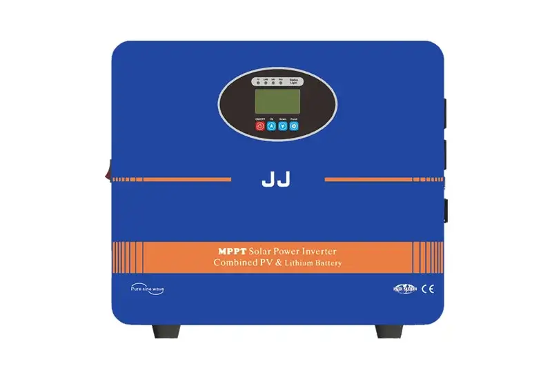
Switching stabilized power supply is a type of power supply that works by using switching transistors to control the output voltage of the power supply, in order to achieve stable output. Its working principle can be divided into the following aspects:
1、 Classification of Switching Voltage Stabilized Power Supply
Before understanding the working principle of switch mode power supplies, we need to first understand the classification of switch mode power supplies. According to different working modes, switch mode power supplies can be divided into AC-DC switch mode power supplies and DC-DC switch mode power supplies.
AC-DC Switching Power Supply: The input voltage is AC power, which is rectified, filtered, and controlled by switches in the input circuit to convert AC power into stable DC power output.
DC-DC switching power supply: The input voltage is direct current, which is processed by switching, filtering, etc. in the input circuit, and then outputs stable direct current to supply to the load.
2、 Working principle of switch tube
In switch mode power supplies, the application of switching transistors is indispensable. Switching transistor usually refers to semiconductor components such as transistors, power field-effect transistors, insulated gate bipolar transistors, etc. It has the characteristics of low static power consumption, high switching speed, and strong controllability.
When we want to control the voltage, the first step is to make the output voltage of the power supply higher than or equal to the required voltage. At this time, the switch tube will be turned on, and the current will enter the inductor through the switch tube. When current passes through an inductor, a magnetic field is formed and an electromotive force is generated on the wires surrounding the inductor. This electromotive force forms a so-called loop oscillation on the capacitor, generating periodic resonant voltages. When the switch tube is turned off, the current in the inductor suddenly interrupts, and the magnetic energy stored in the inductor drives the current to continue flowing, which is then consumed by the load through the output terminal and outputs a fixed voltage. By repeating this process, a stable and controllable output voltage can be formed.
3、 Implementation of Switching Voltage Regulating Circuit
We know that the switching speed of the switching tube is very fast, which can achieve high-frequency switching and has the advantages of energy saving, stability, and high efficiency. In a switching regulator power supply, the first step is to design a switching regulator circuit to control the switching transistor. Then, stable output voltage is achieved through filtering, loop feedback, and other methods.
In switch mode stabilized power supplies, commonly used switch mode stabilized circuits include diode stabilized circuits, inductor stabilized circuits, magnetic component stabilized circuits, etc. Among them, the most common is the inductor stabilized circuit.
The inductive voltage regulator circuit is mainly composed of switch tubes, inductors, capacitors, diodes, and output circuits. Its working principle is the same as above. When the switch tube is conducting, the output voltage can be stabilized through an inductor and then supplied to the load through the output circuit. When the switching transistor is turned off, the energy inside the inductor can be converted into output voltage through the diode and stabilized.
Small and medium power switching stabilized power supplies can be directly driven by transistor circuits, while high-power switching stabilized power supplies require the use of control chips or analog control circuits to achieve precise control.
